The 2016.01-rc1 release is available on GitHub.
Happy new year, everyone! This release includes a number fixes and some great new features. Notable items in this release are:
- A redesigned Object-Oriented MATLAB® interface and Simulink® support via a System Object.
- Support for taming the bladeRF’s on-board VCTCXO via a 1.8V 1 PPS or 10 MHz input
- Support for setting the SMB clock output to an arbitrary frequency.
- Revised and MIT-licensed DC offset calibration routines.
- FX3 firmware updates:
- Upgraded to Cypress FX3™ SDK v1.3.3
- A simple error logging mechanism for the FX3™ firmware.
- XB-100 support for libbladeRF and the bladeRF-cli
- TX-side fixes in libbladeRF
LIBBLADERF_API_VERSIONmacro
For Windows® users, a new installer is available, along with an updated install guide.
Redesigned MATLAB® & Simulink® support
To better serve bladeRF users interested in leveraging MathWorks® products, we’ve re-designed and re-written our support for these tools from the ground up to yield a more intuitive interface and increased performance. We’ve pleased with the results so far, and hope you will be too!
This new implementation has been pulled into the main bladeRF repository and may be found here.
The driving goal behind this implementation was simplicity, in terms of both usability and implementation. We wished to keep the code between the user and libbladeRF as “thin” as possible, to minimize required maintenance efforts. To achieve this, we created a simple Object-Oriented interface atop of libbladeRF using loadlibrary() and calllib() calls to libbladeRF are made by accessing properties of a bladeRF and calling its wrapper methods.
Below are just few snippets to exemplify this new interface. In future blog posts, we’ll cover more advanced usage of both RX and TX timestamp functionality. Note that one can run the command, doc bladeRF, for more information.
MATLAB® Snippets
Query version information:
>> [major, minor, patch] = bladeRF.version; >> fprintf('bladeRF MATLAB bindings v%d.%d.%dn', major, minor, patch) bladeRF MATLAB bindings v0.1.1 >> [major, minor, patch, ver_string] = bladeRF.library_version; >> fprintf('libbladeRF %sn', ver_string) libbladeRF 1.5.0-git-7f6a461 |
Probe and display available devices:
>> devices = bladeRF.devices(); >> for n = 1:length(devices) >> fprintf('Instance: %2d, Bus: %2d, Address: %2d, Backend: %s, Serial: %sn', ... >> devices(n).instance, devices(n).usb_bus, devices(n).usb_addr, ... >> strrep(devices(n).backend, 'BLADERF_BACKEND_', ''), ... >> devices(n).serial); >> end; Instance: 0, Bus: 2, Address: 2, Backend: LIBUSB, Serial: b57e7faa1df48fe26d1bf1df03346708 Instance: 1, Bus: 1, Address: 11, Backend: LIBUSB, Serial: e3f9dbf3143e436542cb0f3ae947caab |
Instantiate a bladeRF object b and connect to the first available device:
>> b = bladeRF
b =

  bladeRF with properties:

          rx: [1x1 bladeRF_XCVR]
          tx: [1x1 bladeRF_XCVR]
      vctcxo: [1x1 bladeRF_VCTCXO]
    loopback: 'NONE'
        info: [1x1 struct]
    versions: [1x1 struct]
xb: 'None' |
The same as the above, but open a device whose serial number starts with “4fb”:
>> b = bladeRF('*:serial=e3f');
Configure RX parameters:
>> b.rx.frequency = 915.25e6; >> b.rx.samplerate = 5e6; >> b.rx.bandwidth = 3e6; >> b.rx.lna = 'MAX'; >> b.rx.vga1 = 30; >> b.rx.vga2 = 5; |
Run DC Calibrations
>> % Run all LMS6002D calibration >> b.calibrate('ALL'); >> % Calibrate at the current frequency. Note that frequency lists can be used. >> % See 'help bladeRF_IQCorr.auto_dc' >> b.rx.corrections.auto_dc(); ans = -32.0000 576.0000 0.0002 0.0004 |
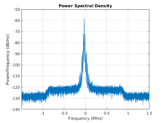
Receive and plot the FFT of 50,000 samples:
>> b.rx.start(); samples = b.receive(50e3); b.rx.stop(); >> pwelch(samples, [], [], b.rx.samplerate, 'centered'); |
Example result: Stereo FM from a wireless headphones
Deallocate bladeRF object b and close the device:
clear b; |
Note: The device is only closed once all handle references have been cleared. (MATLAB inherently provides reference counting of handles.)
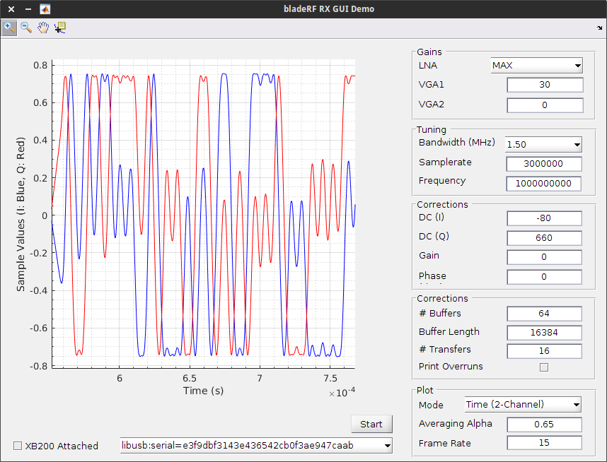
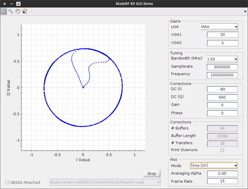
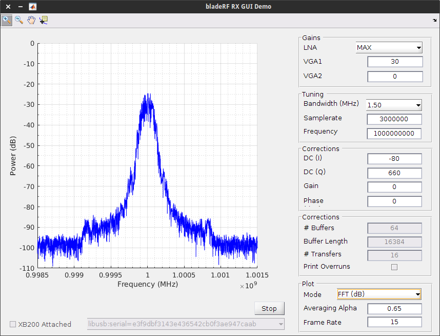
bladeRF_rx_gui Demo
The bladeRF_rx_gui.m example puts together the above concepts to create an interactive GUI that provides access to various device properties while displaying
live plots. Here are a few screenshots of it in action:
Simulink® System Object
The bladeRF_Simulink.m file implements a System Object that can me used in am model file via the MATLAB System. Instructions near the end of the Windows® Install Guide describe how to place this in a model and to configure it to RX, TX, or both.
We’ll plan to post more about this in future posts.
VCTCXO Taming via 1 PPS or 10 MHz input
In terms of stability, we’ve been quite pleased with the VCTCXO we’ve used on the bladeRF. However, oscillators will eventually age over time and drift from their calibrated frequency. Furthermore, many bladeRF users are interested in celluar applications, which require significant frequency accuracy.
Thanks to the excellent work of Brian Glod, FPGA v0.5.0 now includes the ability to continuously tame the VCTXCO using a 1.8V 1 PPS or 10 MHz input signal supplied via J71 pin 1. The libbladeRF functions, bladerf_set_vctcxo_tamer_mode() and bladerf_get_vctcxo_tamer_mode() may be used to enable and configure this functionality.
The same can be done in the bladeRF-cli:
bladeRF> set vctcxo_tamer 10MHz

  VCTCXO tamer mode: 10 MHz

# Wait some amount of time. More than 10 seconds should provide a
# very rough VCTCXO trim DAC estimate. 10 minutes should yield
# a more accurate estimate.

bladeRF> print trimdac
 Current VCTCXO trim: 0x8759
 Stored VCTCXO trim:  0x8b28
As we can see in the above, the nominal VCTCXO trim DAC value has deviated slightly from the factory calibrated value. Below we show how to update the value in flash for a bladeRF x40 device. (Simply change the “40” to “115” for an x115.)
bladeRF> set vctcxo_tamer off

  VCTCXO tamer mode: Disabled

bladeRF> flash_init_cal 40 0x8759
[INFO @ usb.c:498] Erasing 1 blocks starting at block 3
[INFO @ usb.c:503] Erased block 3
[INFO @ usb.c:511] Done erasing 1 blocks
[INFO @ usb.c:705] Writing 1 pages starting at page 768
[INFO @ usb.c:709] Writing page 768
[INFO @ usb.c:718] Done writing 1 pages
bladeRF> quit
Below is a picture of a setup using a Leo Bodnar Precision Frequency Reference (GPS Clock),
configured for a 10 MHz output with 16 mA drive strength (configuration). Because this device provides a 3.3V signal and the FPGA input requires 1.8V, a 10 dB attenuator is used. Although the resulting voltage is closer to 2.0V, this is still well within the acceptable limits of the associated Cyclone IV IO bank. (We don’t recommend going much higher, however.)
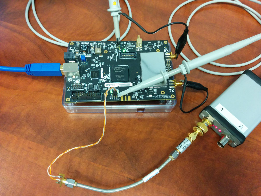
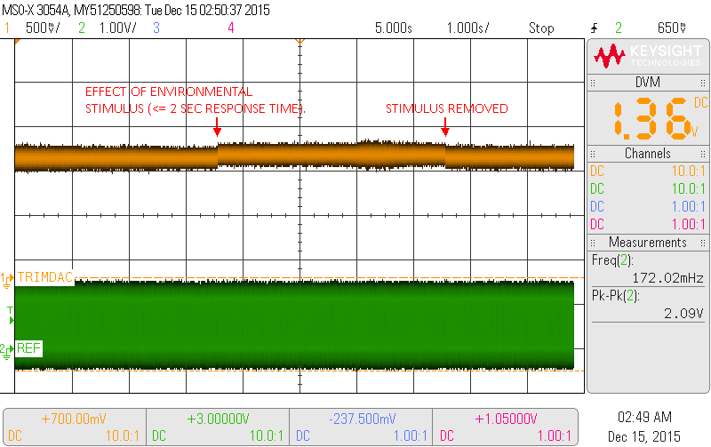
As shown above, J71-1 is connected to the 10 MHz output, through the attenuator. J72-2 is a connection to ground. One oscilloscope probe is monitoring the VCTCXO trim DAC voltage, via TP40. Another is monitoring the input on J72-1.
We can monitor the VCTCXO tamer via the trim DAC voltage, as shown in the following oscilloscope captures. In the first capture, we can clearly see the different stages of the tamer implementations. Prior to enabling the tamer, we see the factory calibrated value, which is quite close to the final result!
Once the tamer has been enabled, it first calculates the frequency errors obtained when using the minimum and maximum VCTCXO trim DAC values. The tamer then makes an initial coarse guess at the required trim DAC value using a linear approximation of the frequency-error response.
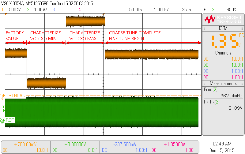
After obtaining an initial guess the tamer begins running a continuous fine tune operation. In this stage, the tamer tracks frequency error over 1-second, 10-second, and 100-second intervals and updates the VCTCXO trim DAC value, based upon the magnitude of the detected error.
In the below capture, we can see the tamer reacting to an environmental stimulus, in which warm air was blown at the VCTCXO. In response to this stimulus, the tamer slightly increases the trim DAC voltage to compensate. It then reduces it once the stimulus has been removed.
Arbitrary SMB Output Frequencies
It is now possible to configure the bladeRF’s SMB clock output to generate arbitrary frequencies, thanks to a patch set kindly provided by Adam Greig. This functionality is exposed via the following libbladeRF functions:
- bladerf_set_rational_smb_frequency()
- bladerf_get_rational_smb_frequency()
- bladerf_set_smb_frequency()
- bladerf_get_smb_frequency()
This can be achieved in the bladeRF-cli via an added optional frequency argument to the set mimo command:
set mimo master <frequency>
DC offset calibration routines
The DC offset calibration routines have been revamped to address some of the issues reported on our GitHub tracker and to yield improved performance. In the near future we’ll be adding the ability to perform the TX calibration in an external loopback configuration; this should help yield even better results on the transmit side. On the RX side, we recommend disconnecting and/or terminating the RX input when performing this calibration.
In order to allow users to integrate these routines (and modifications) into their own projects, they have been relicensed under an MIT license. You can now find dc_calibration.h and dc_calibration.c in the bladeRF repository’s host/common directory.
Firmware Updates
The FX3™ firmware and its associated build have been updated for version 1.3.3 of the SDK. For those developing firmware modifications, the only required changes are likely a change of FX3_ROOT in the toolchain.mk file.
To assist with debugging, a simple logging mechanism has been added to the firmware. This log may be accessed via the libbladeRF bladerf_get_fw_log() function. The bladeRF-cli provides a fw_log command atop of this function.
XB-100 Support in libbladeRF and bladeRF-cli
The XB-100 was originally intended to help folks developing on the FPGA access a few spare I/O pins while debugging. However, there’s been some interest in using this for other purposes, such as controlling a T-R switch (with proper isolation and logic level conversion, of course) from host software.
bladerf_expansion_attach() now supports the XB100, and convenience macros for I/O mappings the XB100 and XB200 have been added. It is possible to access a subset (including a single pin) of the expansion port I/O via these libbladeRF functions and macros.
The bladeRF-cli exposes these functions via the xb_gpio and xb_gpio_dir, and allows either the entire GPIO (direction) register to be accessed, or an individual pin to be accessed. More information about this can be found here on our wiki.
TX Buffering Fixes
This latest release includes an important fix that addresses a defect in which not all available TX-side buffers were being utilized. If you had previously run into any issues pertaining to transmit underruns, please give these latest changes a shot.
LIBBLADERF_API_VERSION macro
Per request, we’ve introduced a LIBBLADERF_API_VERSION macro to libbladeRF.h to better allow developers to test for the availability of some of the aforementioned new API features at compile-time.
Wrapping Up
While keeping busy, we know we let our blog become a bit inactive. One of our New Year’s resolutions is to change this, and we certainly appreciate any help that members of the SDR community would like to offer. If you have a project or product using the bladeRF, please feel free to contact us to tell us all about it. We’d be happy to give it a spin and post about it here.
As always, thank you so much to everyone in the community for contributing fixes, bug reports, feedback, suggestions, and so much more. In particular, we’d like to thank:
- Dr. Juan R. Pimentel (Professor of Computer Engineering, Kettering University) for his contributions to our SDR-based FRS Transceiver write-up.
- Mathieu Rene for his efforts in adding API support for controlling the FPGA RX FIFO Mux and for improvements to the FPGA’s internal loopback.
- Adam Greig for his SMB output patch set.
Cheers,
Jon (jynik)
Recent Comments