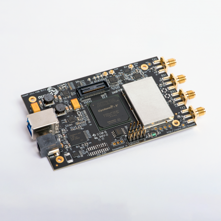
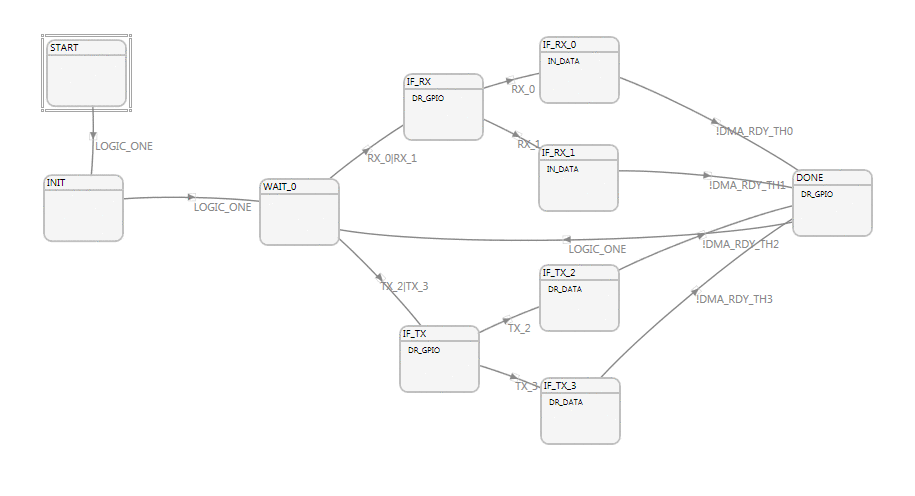
The FX3 contains a peripheral known as the GPIF, which is a 32bit 100MHz state machine based bus. This core has access to 4 DMA channels to the rest of the FX3 and executes independent of the on-chip ARM microcontroller. To use the GPIF to transfer data between the FX3 (subsequently the host PC) and the FPGA a state machine was designed using the GPIF Designer (available from Cypress). Since the bladeRF can operate at full-duplex a versatile state machine had to be designed, keeping in mind the limitations of the FX3. Fortunately, the FX3 offers DMA double buffering, which allows the GPIF to read data using one DMA channel while allowing another DMA channel to copy data from USB endpoints. Double buffering both RX and TX allows the bladeRF to fully saturate the GPIF bus, allowing for nearly 400MB/s data throughput.
Due to a limitation of the GPIF, the FPGA keeps a single bit of state that indicates which RX and TX DMA channels were used last. States IF_RX_0, and IF_RX_1 read data from the GPIF using DMA channels 0 and 1 respectively, and move it in internal DMA buffers, while states IF_TX_2 and IF_TX_3 write data to the GPIF. To operate at maximum efficiency in full-duplex mode the GPIF will likely have one TX and one RX buffer being sent over USB as another set of RX and TX buffers are being operated on by the GPIF. Due to the round-robin DMA channel selection requirement of the FX3, GPIF data read operations have to alternate between utilizing DMA channels 0 and 1 to push data to the FX3; the same applies to GPIF write operations, which in this application have to alternate between IF_TX_2 and IF_TX_3 (DMA channels 2, and 3). To further complicate issues, the delivery of USB packets is not guaranteed to be interlaced, so it unlikely that a USB BULK IN packet will follow a USB BULK OUT packet therefore the state machine has to be versatile to anticipate executing multiple GPIF data reads followed by multiple GPIF data writes.
Keeping all of this in mind, the solution we chose was to have the FPGA be notified of which DMA channels have data, and which are free. This way the FPGA can also control the state machine to tell it which DMA channels to use; the GPIF state machine does not have general purpose registers or enough specific purpose registers to keep track of scheduling all 4 DMA channels in such a way.
Once flashed to the FX3, the Cyclone 4 FPGA was instrumented using SignalTap and the GPIF bus was analyzed. Signals ctl[8] and ctl[11] are indicators that the GPIF is consuming data buffers from DMA channels 2 and 3, respectively. Signals ctl[10] and ctl[12] show the GPIF sitting idle. Signals ctl[6] and ctr[7] are DMA empty status flags belonging to DMA threads 2 and 3, respectively.
The maximum throughput of the GPIF can be calculated by measuring the amount of time elapsed between sequential 1024-cycle 32-bit buffer transfers. By selecting the start of the first full buffer at time 1088 (1024+64), and subsequent data buffer as starting at roughly 2432, the elapsed time is calculated to be 13.44 microseconds. Transferring 1024 * 32bit in 13.44 microseconds corresponds to a throughput of 290MB/s.


Recent Comments