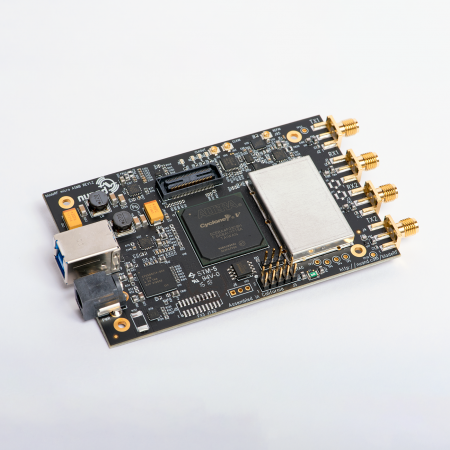
If you are attending DEFCON 32, meet us at our DEFCON vendor booth to have your bladeRF 2.0 micro calibrated!
Fully characterized test equipment has long been a gold standard, so we are happy to be bringing a low-cost full gain calibration to the bladeRF 2.0 micro! Gain calibrated bladeRFs can be used to transmit at precise output power levels, and to accurately measure the power of received RF signals – the bladeRF basically becomes a power meter!
Please note that while the gain calibration API and the power measurement tools are now available, your devices will require calibration. Please sign up for the waitlist for more information regarding calibration services at https://www.nuand.com/product/bladerf-2-0-micro-calibration-service/ .
Characterizing the Frequency Response
The goal is to flatten the TX and RX frequency response for a given bladeRF’s operating frequency range. This largely helps with wideband systems and RF power measurement applications. The most practical way for us to achieve this is by implementing a gain compensation algorithm against its frequency response characterization. Ideally, RX set to a gain of 0dB could be converted directly from dBFS to dBm and TX should stay close to 0dBm provided a CW at a magnitude of +-2047.
Characterizing the Frequency Response
We need to know what power the bladeRF outputs and what relative power is received across its frequency range to characterize it. A programmable vector signal transceiver (VSA + VSG) helps us out here. It could be programmed to TX and RX at the same frequency as the bladeRF with a known power output and input. So we program it to run a few sweeps at different gains across both of its TX and RX channels.
The results are stored in a CSV and, more cleanly, in a bladeRF .tbl format to be loaded into libbladeRF.
Calibration Data to libbladeRF
With the characterization complete, the calibration tables are ready to be imported. There are two calibration files. One for TX and one for RX due to their different measurement methodologies. Using bladerf_load_gain_calibration(), we can load either a CSV or a .tbl calibration file with libbladeRF.
The content of the gain calibration data is loaded into a channel specific struct that the device handle points to. As frequency and gain settings are changed through libbladeRF, the correction factor is determined by using linear interpolation between two of the closest calibration entries. libbladeRF subtracts the correction factor from the requested gain, and the actual gain will either be adjusted by the correction factor or as close as it can get to the corrected gain within the bound of the bladeRF’s gain range. This way the bladeRF does not compromise on dynamic range.
Getting Started
Git clone the latest bladeRF repo code, and ensure the bladeRF-power commits are in the git log!
Once your device is calibrated and the calibration files are available on Calibration, download the RX and TX gain tables into your Nuand directory (https://www.nuand.com/libbladeRF-doc/v2.5.0/configfile.html), ~/.config/Nuand/bladeRF on Linux and C:\Users\USERNAME\AppData\Roaming\Nuand\bladeRF on Windows.
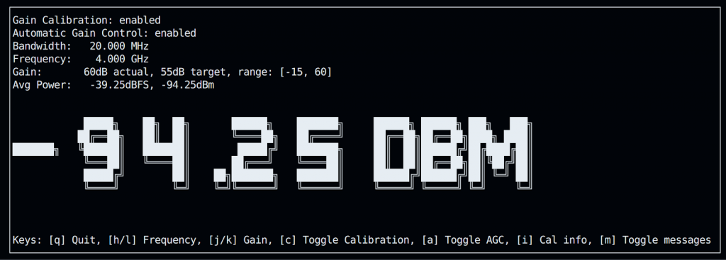
The easiest way to get familiar with how gain calibration works is by experimenting with the bladeRF-power application. bladeRF-power turns the bladeRF into a power meter with a variable resolution bandwidth reaching up to 61.44MHz and over 100dB of dynamic range when automatic gain control (AGC) is enabled!
Toggling gain calibration, changing the bandwidth, toggling the AGC, and adjusting the gain should put you in a good spot for understanding how the relationship between the gain calibration interplays with different device assignments.


