We have spent the last couple of weeks further developing the platform and talking with part distributors. All of our parts at this point are in stock, and those that aren’t have reasonable lead times. We are taking these steps to ensure that if we do go to mass production there will be no hiccups.
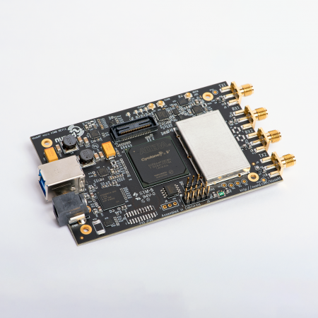
As for some other exciting news, we recently got our hands on the first of several pieces of test equipment we will need to develop our intended examples and expansion boards. Having this sort of equipment at home is much more convenient than constantly scheduling lab time weeks in advance!

As a sanity check, we ran a conducted RF chirp on the bladeRF at 500MHz to see its maximum bandwidth capabilities. In previous experiments, we have seen about 28MHz of occupied bandwidth, which this run seems to agree with.

The spectrum analyzer was used to capture a spectrum of spurs over the bladeRF’s frequency range on the RX side. Besides the occasional spur, the noise floor of the device is surprisingly good.

Here is the same sort of spectrum capture but on the TX side, and again the spectrum looks pretty clear with the exception of a few spurs which appear to be related to the main 38.4MHz clock. Spurs this low on the TX side really don’t matter since they are so far down below the TX output power of the LMS that they will no be able to significantly interfere with any transmissions or even influence

Good work guys!
I’m glad to hear LimeMicro chip is used in one more open-source project 🙂
Could you clarify what exactly have you measured at your NF pictures? It’s not exactly clear from your description.
Thanks Alexander!
The noise floor plots show the spectrum taken right at the TX and RX differential pairs of the LimeMicro chip. The plots are meant to show the overall quietness of the board even as the digital circuits on the other half of the board are running.