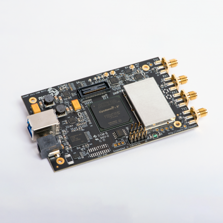
bladeRF-fsk is a host-software based modem utility implemented with continuous-phase frequency shift keying (CPFSK) modulation. It functions as a text chat or file transfer program between bladeRFs with a raw link rate of 250 kbps, originally released as part of the bladeRF github repository in 2016.
We’ve now given bladeRF-fsk necessary updates to make it fully functional on the bladeRF 2.0 micro. Additionally, we fixed bugs in the modem and added new features such as SNR estimation, configurable packet size and sample rate, and AGC support. BladeRF FPGA bugs that affected bladeRF-fsk have also been fixed and the program is now bug-free on bladeRF 1 & 2.
This post steps through the bladeRF-fsk modem design. Instructions for building and running the modem can be found in the README.
Modem details
The bladeRF-fsk modem is implemented fully in C code in a standalone program running on the host computer, which uses libbladeRF to configure the bladeRF and send/receive baseband IQ samples through USB connection. These baseband IQ samples are up/down-converted to radio frequency on the bladeRF’s RF transceiver chip and transmitted/received through the air. The modem serves as an example project for the SDR community.
The modem’s code has been moved to a separate repository here, which is pulled into the main bladeRF repository as a git submodule. The modem’s repository includes a MATLAB/Octave model and simulation of the modem. The simulation was used to generate the plots shown in this post.
The figure below shows the bladeRF-fsk processing pipeline with the default sample rate of 2 Msps.
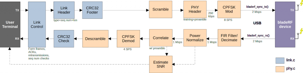
bladeRF-fsk modem processing pipeline
Link Layer
The link layer packetizes data into discrete frames and handles guaranteed delivery of frames by waiting for acknowledgements sending retransmissions if no acknowledgement is received. Sequence numbers are also checked in order to discard potential duplicate frames at the receiver (for example if an ACK is received with errors and the transmitter resends the frame). Payload length is fixed to the size specified in command line arguments (default 1000 bytes), but a length field in the header indicates how much of that payload is valid (the rest is zero padded).
While there is no forward error correction, frame error detection is implemented with CRC32 checksums, and frames received with CRC errors are resent repeatedly, only giving up once attempts are exhausted.
Physical (PHY) Layer
TX
The PHY layer applies scrambling (XOR with pseudorandom scrambling sequence) to reduce repeated 1s and 0s, and adds a training sequence to allow power normalization and AGC to stabilize, along with a preamble for synchronization, before performing CPFSK modulation on the frame.
Modulation is accomplished via a lookup table with 32 sample points around the IQ unit circle; the phase is rotated 1/4 revolution (pi/2 radians) either counter-clockwise for 1 (positive phase change = positive frequency) or clockwise for a 0 (negative phase change = negative frequency). This is kind of like controlling the hand of a clock. Subsequent symbols are rotating starting from the ending point of the previous symbol, meaning there are no discontinuous phase jumps, which is why this is continuous phase FSK.
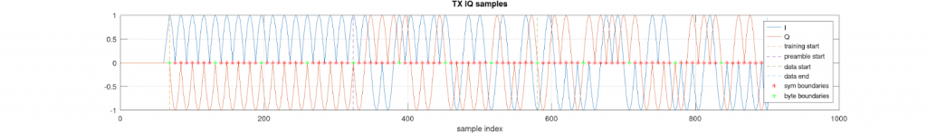
TX baseband IQ samples for PHY frame with payload message “hello”
After passband upconversion to RF, these 1s and 0s become positive and negative frequency deviations around the carrier frequency. With 8 samples per symbol at the default sample rate of 2 Msps, the frequency deviation is +/- 62.5 kHz, although the full bandwidth of the signal spreads out much wider than that due to 1<->0 symbol transitions causing abrupt changes in direction of the phase rotation, which adds extra spectral content besides the two deviated frequencies. The main lobe bandwidth is 375 kHz, and decaying side lobes extend out to the full 2 MHz bandwidth produced by 2 Msps IQ, truncated to 1 MHz (bladeRF 2) or 1.5 MHz (bladeRF 1) from the anti-antialising filter after the DAC. The side lobes don’t carry much information and are swallowed by noise then mostly filtered away in the receiver.
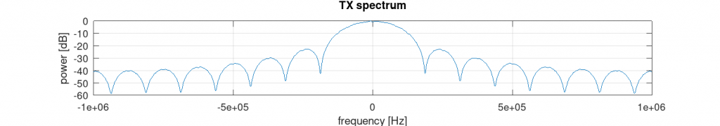
TX baseband spectrum
RX
IQ samples received from the bladeRF are first decimated 2X using a channel FIR filter. The filter reduces out-of-band noise (increasing SNR) and removes excess bandwidth beyond the main lobe and first sidelobe, also allowing the 2X downsampling to be performed without aliasing. The filter only processes output samples that will not be thrown out by downsampling, effectively reducing the sample rate 2X at the input to the filter rather than at the output, speeding up filter processing. Power normalization uses an IIR filter to estimate the running signal power and apply an inverse gain such that the output power is normalized to 1.0 (meaning the signal limits are roughly +/- 1.0, represented by +/- 2048).
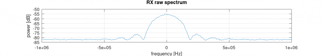
RX raw baseband spectrum (15.5 dB SNR)
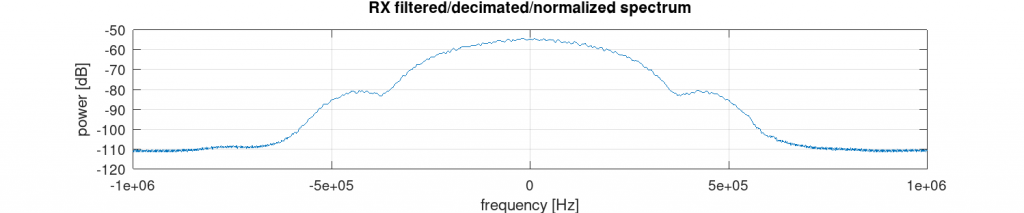
RX filtered/decimated/power normalized spectrum (23 dB SNR)
Frame synchronization is accomplished with correlation against the known preamble, with the correlation power compared to a fixed threshold to detect the start of each frame. A “countdown” routine ensures the correlation peak is selected rather than the shoulder. After detection, timing is locked until the end of the frame, no symbol timing or carrier frequency tracking loops are needed.
SNR estimates are produced using the estimated power after the preamble (the signal+noise power) along with the estimated noise power just after the end of the frame. Signal power is computed by subtracting the noise power from the signal+noise power. It may not always be accurate depending on how quickly the AGC adjusts itself after the frame ends.
CPFSK demodulation is performed by calculating the phase angle of each IQ sample using atan(), and measuring the total change in phase over the length of the symbol. A positive phase change (positive frequency) is demodulated as a 1. The nature of FSK modulation makes it immune to minor carrier frequency offsets, since the frequency deviation (phase change) only needs to have the correct sign to demodulate properly.
The first byte is demodulated to determine the frame type (data or ACK), which determines the number of bytes to demodulate (ACK frames are only 7 bytes). After descrambling by XORing the demodulated bits with the known scrambling sequence, the recovered frame is passed to the link layer.
User Interface
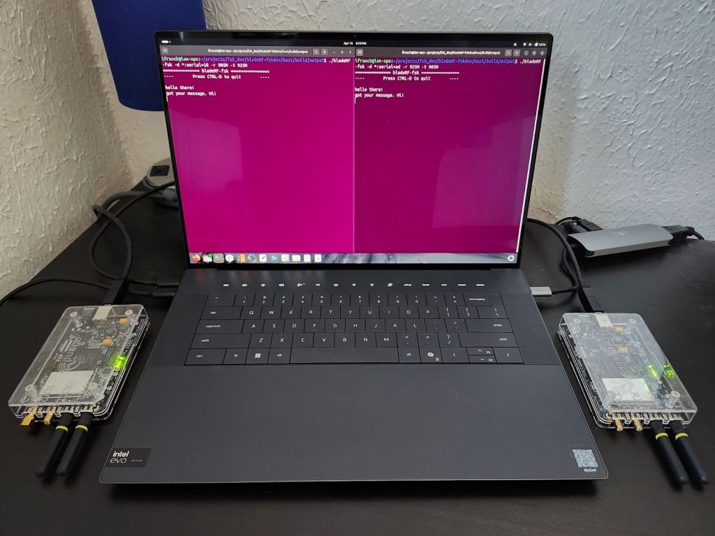
The program (bladeRF-fsk) runs on the terminal which acts as the user interface, allowing the user to either enter text with their keyboard (stdin) or pass in a file with -i to be transmitted. Received data is either printed to the terminal or written to the filename provided by -o. More details on how to run the program are provided in the README.

bladeRF-fsk in action with two radios exchanging chat messages
Code structure
The code is structured essentially as object-oriented C, where each major file performing a function (link, phy, fsk, fir_filter, correlator, etc), has an object “handle” that is passed around and tracks the state. Each handle is constructed by allocating memory, initializing fields, starting threads, and constructing any sub-objects (such a phy handle living inside the link handle). The handle is closed at the end, freeing allocated memory, turning off threads, and closing any subhandles.
The code utilizes multi-threading with pthreads, allowing multiple operations to run in parallel. For example, the PHY receiver runs on its own thread constantly receiving samples and processing them; RX and TX are on separate threads so they never get in each other’s way. The TX and RX pipelines each have 3 threads running, representing user interface (bladeRF-fsk.c), link layer (link.h), and phy layer (phy.c).
New features
The new release of bladeRF-fsk includes the following updates:
- Full bladeRF 2.0 support
- biastee amplifier support
- channel selection between the 2 sets of TX/RX ports
- AGC support and unified gains
- By default, AGC is enabled on both bladeRF 1 & 2. To disable it, set the gains manually using –rx-gain
- Unified gain support for bladeRF 1 & 2
- SNR estimation
- SNR estimated during each received frame (can be printed out with BLADERF-FSK_ENABLE_NOTES_PHY cmake build option)
- Average SNR prints out at end of session when program quits
- Adjustable packet size
- Use -p to adjust the packet payload data size per frame (default 1000 bytes)
- Adjustable sample rate
- Use -s to adjust the sample rate (default 2 Msps)
- 2X decimation in receiver
- Reduces processing load 2X in FIR filter, power normalizer, and FSK demod, with no reduction in performance
- Debug features
- Ability to log TX or RX samples to file with BLADERF-FSK_LOG_TX_SAMPLES and BLADERF-FSK_LOG_RX_SAMPLES cmake build options
- Other hidden debug features via defines in link.h and phy.h (see the comments)
- Bug fixes
- Corner case RX bugs fixed causing corrupted bytes
- Unrelating FPGA bugs causing failures in bladeRF-fsk fixed
- Code cleanup