
bladeRF-wiphy is an open-source IEEE 802.11 compatible software defined radio VHDL modem
If you like the bladeRF-wiphy project, please consider starring it on Github!

What is the bladeRF-wiphy project?
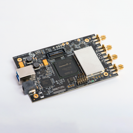
The bladeRF-wiphy project is an open-source IEEE 802.11 compatible software defined radio VHDL modem. The modem is able to modulate and demodulate 802.11 packets (the protocol WiFi is based on), and run directly on the bladeRF 2.0 micro xA9’s FPGA.
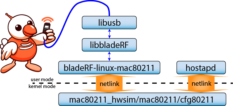
The bladeRF-wiphy coupled with Linux mac80211 allows the bladeRF 2.0 micro xA9 to become a software defined radio 802.11 access point! 802.11 packets (PDUs) are modulated and demodulated directly on the FPGA, so only 802.11 packets are transferred between the FPGA and libbladeRF.
NOTE: While a JTAG adapter (USB-Blaster) can help with understanding the modem at run-time, a JTAG adapter is not necessary to run the RBFs linked below.
For instructions on compiling, installing, and running bladeRF-wiphy, take a look at the bladeRF-wiphy instructions . To simulate bladeRF-wiphy take a look at the bladeRF-wiphy simulation guide.
Why write and run a modem on the FPGA of a software defined radio?
While implementing a modem in HDL is much harder than a modem written entirely in C or Python, HDL and FPGAs allow for one of the most crucial aspects of modem development: low latency and timing control.
In IEEE 802.11, specifically there is a requirement that a receiving modem (be it a client STA, or access point AP) must acknowledge the successful reception of an incoming packet addressed to it by beginning to transmit an an ACK packet within 10 microseconds of the end of the incoming packet. It is impractical, or at times outright impossible to meet such narrow timing requirements with C and Python soft-modems because of the relatively high latency of data buses at bandwidths needed to stream raw IQ samples. Even high-speed buses such as PCIe and USB add too much latency if IQ samples have to be sent over a bus, processed by a CPU, and a response sent back over the same bus. This situation is less than ideal when compared to an HDL modem, where a developer has full deterministic and “clock-cycle precision” control over the latency and timing of signals in the modem. HDL modems also benefit from massive parallelization that can be achieved in FPGAs. The level of control and performance in this case makes HDL modems uniquely capable of handling the task of generating an ACK response within 10 microseconds.
It is worth noting that lean HDL modems tend to utilize fixed point arithmetic in their DSP pipelines, which is in stark contrast to soft-modems written in C, Python, etc which mostly use floating point arithmetic to benefit from accelerators such as AVX (in CPUs) and GPGPUs. One example of such an accelerator toolbox is GNURadio Volk ( https://github.com/gnuradio/volk ). The main driving force behind the fixed point arithmetic in HDL modems is the comparatively massive logic resource utilization of floating point arithmetic in FPGAs.
HDL modems may end up running on FPGAs or converted into ASICs, but early in the development process, HDL modems can be prototyped as soft-modems. MATLAB, GNURadio, and Python are popular choices for the first stage of design due to the standard flexibility of software development. Once the theoretical performance for modem is validated, the DSP algorithms developed in the previous step can be implemented again as floating point implementation. Afterwards, the floating point implementation can then be implemented again as fixed point arithmetic in a compiled language such as C. While this step is optional, having a fixed point implementation is useful because it can be compiled and validated quickly to ensure it behaves as well as the best theoretical modem designed in the previous step. The developer can then easily debug the difference between a “known good” fixed point implementation (the one written in C) and the HDL modem; this is known as having “bit level accurate” implementations. Ideally, in the development process this allows for fast iterations of the fixed point C implementation of the modem by allowing BER and PER curves to be quickly generated based on millions of simulated packets; tests can finish in just minutes. Simulating an HDL modem in its entirety to generate BER and PER curves is generally several orders of magnitude slower.
How does WiFi work?
What we call WiFi is a very tall stack of technologies that stretches from high layer protocols that use TCP and UDP (layer 4) like HTTP (Layer 7), down to a Medium Access Control (MAC) that coordinates access and authentication (roughly Layer 2), down to a modem (the Physical Layer, PHY), that translates between digital bits and analog RF signals (Layer 1); a modem that in no small part has to deal with and mitigated effects dictated by Maxwell’s and Schrodinger’s equations.
The entire WiFi stack can be split up into two equally important parts, the PHY and the MAC. The PHY is essentially responsible for translating between digital packets (PDUs) and baseband IQ samples. Packets going in and out of the PHY are then processed by the MAC to establish link state, and higher level protocol functions (e.g. beaconing, authentication, association, and data passing).
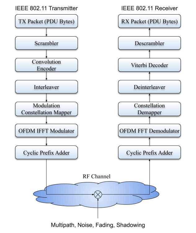
The PHY, as defined by the IEEE 802.11 specification, is generally an OFDM waveform consisting of subcarriers modulated either as BPSK, QPSK, 16-QAM, 64-QAM, or most recently 256-QAM. The PHY is responsible for modulation PDUs (packet data units, essentially an 802.11 frame) to raw baseband IQ samples, and demodulation raw baseband IQ samples to PDUs). The PHY’s transmit process is relatively straightforward, the PHY does not concern itself with the contents of the packet it is asked to transmit by the MAC. So with little to no modifications the PHY begins modulating the digital payload, the PDU, into raw IQ samples and awaits for an opportunity to transmit. On the receive side, the PHY is constantly analyzing signals and awaits the beginning of an 802.11 packet, in a process called acquisition. The 802.11 preamble, which is present at the very beginning of any IEEE 802.11 RF frame consists of 10 short training sequences and 2 long training sequences. The receiving PHY uses the training sequences to understand (estimate in DSP terminology) what happened to the signal as it was transmitted over the air. Multipath, fading, Doppler shifts (and consequently Doppler spreads) can greatly distort signals, however having a known preamble allows a receiver to both positively identify a packet as belonging to its protocol, and understand what it must do to undo the effects of the channel on the signal. For receiving 802.11 frames, the bladeRF-wiphy estimates acquisition, symbol timing, channel offset correction, and channel impulse response parameters. Most of the complex DSP and statistical theory applied in a modem (comprised of both RX and TX) is in the receiver. This is also why it is good practice to begin the design process with a transmitter.
Once two 802.11 modems are able to exchange packets effectively, things quickly start resembling wired communications like Ethernet (IEEE 802.3). There is however a key difference with wireless communication, everything shares just one finite medium — the RF spectrum, which is readily accessible by anything within range. The 802.11 specification requires devices to be mindful of this, and the solution is relegated to the MAC. Essentially, the MAC in an 802.11 device maintains the state of the link by exchanging management frames. An access-point advertises its existence (and includes information for sleeping clients) in period beacon frames, a type of management frame. Conversely, a station (STA) that wants to connect to an AP, must go through the association process: optionally exchanging probe requests and responses with the AP, exchanging authentication management frames, and ultimately association management frames. Assuming an open SSID, as long as the STA occasionally transmits data to the AP or successfully receives packets by sending ACKs back to the AP, the link will remain established until either the AP or the STA exchange deauthentication (“deauth”) or disassociation management frames. While the link is established the AP and STA exchange 802.11 frames, which effectively is at the same layer as Ethernet.
As a quick side note, Linux has an entirely open-source 802.11 MAC implementation known as mac80211 ( https://wireless.wiki.kernel.org/en/developers/documentation/mac80211 ). BSD systems also have their own implementation known as net80211 ( https://wiki.freebsd.org/WiFi ). On Linux, mac80211 is able to behave both as an AP and an STA. The mac80211 subsystem can be queried through the cfg80211 subsystem with familiar tools like iwconfig and the iw tools (iw, iwconfig, iwlist, etc).
How does the bladeRF-wiphy modem work?
The bladeRF-wiphy modem is organized into two major modules wlan_tx and wlan_rx (respectively the modulator and the demodulator), which are unified under wlan_top. The wlan_top module also implements queuing and deqeueing of packets, Distributed Coordination Function (DCF) and Acknowledgement (ACK) mechanisms.
The names of the subsections below mostly correspond to modules found in the fpga/vhdl directory in bladeRF-wiphy.
wlan_top:
The wlan_top module instantiates the three core components of the bladeRF-wiphy IEEE 802.11 compatible modem, including the RX, TX, and DCF modules. The DCF module constantly determines if it is feasible for the current modem to transmit if it wanted to. Depending on the type of packet a transmitter intends to transmit, it will have to wait an amount of time dictated by either Short Interframe Space (SIFS) or DCF Interframe Space (DIFS). An IEEE 802.11 modem must respond with an Acknowledgement (ACK) frame for each received frame that is addressed to it. The hard limit defined as SIFS, requires that the transmission of the ACK frame begin with 10 microseconds of the end of the received frame. During the SIFS time, other IEEE 802.11 modems that received the original frame know to give the intended recipient time to generate an ACK packet. If however, the current modem wants to transmit because it has a data frame or management frame, it must wait an amount of time defined as DIFS before it can transmit. Initially, DIFS is between 20 and 50 microseconds but if the medium is inaccessible, the wait can grow exponentially to many milliseconds due to the exponential backoff algorithm. wlan_top’s RX state machine waits for decoded packets from wlan_rx and translates them into the standard packet_control_t interface for exchanging digital payloads through libbladeRF. In case the wlan_rx core determines it needs to send an ACK frame, it asserts ack_mac and ack_valid with the original transmitter’s MAC address that must receive an ACK packet. wlan_top’s TX state machine waits for the DCF to tell it when it can transmit. If there are any ACK packets, the TX state machine waits a SIFS amount of time prior to transmitting. If however, any other kind of data or management frame is meant to be transmitted, the TX state machine will wait for an amount of time set by DIFS.
In case the modem does have something to transmit but the medium (the RF channel) is currently busy, the DCF implements an exponential backoff algorithm that successively waits up to twice as much as the previous waiting period to transmit. The idea behind exponential backoff is to avoid a thundering herd of contention between multiple transmitters, when many blocked transmitters simultaneously notice they can transmit due to the medium being usable again.
This process is known as Carrier Sense Multiple Access / Collision Avoidance (CSMA/CA).
wlan_tx:
wlan_tx_controller:
The wlan_tx_controller module is the primary of two main state machines in the transmit chain. Its primary purpose is to generate the preamble and await its completion, prior to starting the wlan_framer module. A standard 802.11 frame’s preamble consists of 10 Short Training Sequences (STS) followed by a 0.8 microseconds Cyclic Prefix (CP) for two 3.6 microsecond long Long Training Sequences (LTS). wlan_tx_controller asserts short_start to start the STSs, and awaits for long_done before asserting encoder_start to start the wlan_framer module. After wlan_framer is started, wlan_tx_controller waits for indication the packet has finished being modulated.
wlan_framer:
The wlan_framer module is primarily responsible for receiving PDU bytes and sending them to the modulator. wlan_framer receives control of the transmit chain right after preamble is finished being generated. The first symbol generated by wlan_framer is the SIGNAL symbol. The symbol is based on tx_vector, a metadata HDL signal that informs the modulator how long a PDU is and its intended transmission MCS. The SIGNAL symbol decodes to 3 bytes, these 3 bytes include fields that determine the length of the packet, and the modulation and coding scheme of the following OFDM symbols. It should be noted, the SIGNAL symbol is always modulated at 6Mbps rate.
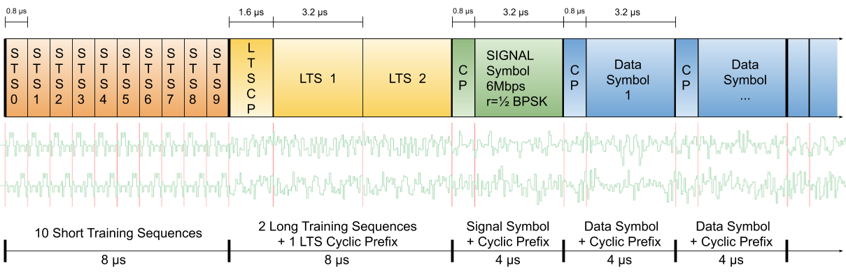
To put into perspective the end goal wlan_tx_controller and wlan_framer are trying to achieve in outputting, below is an illustration of a typical IEEE 802.11 burst. A typical burst includes the preamble (which is used by the receiver to estimate symbol timing, center frequency offset, and the channel impulse response), and data symbols (the first of which is the SIGNAL symbol, followed directly by symbols that encode the payload data). The waveforms in green which appear below the block diagrams are example IQ samples generated by wlan_tx.
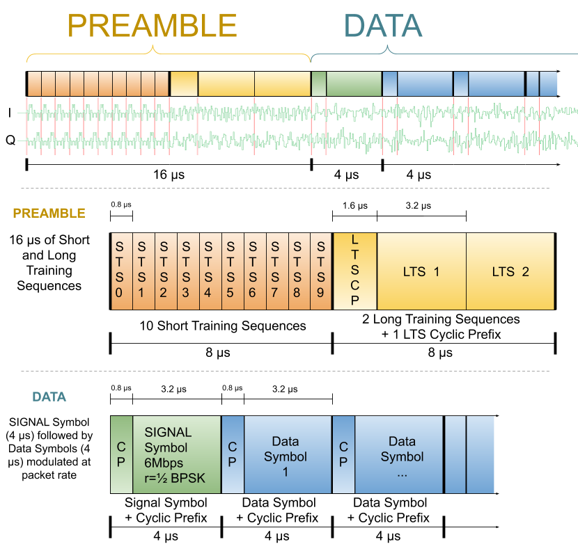
Putting it all together into one diagram:
The wlan_framer state machine prepares enough bytes to generate one OFDM symbol at a time. After dispatching enough bytes, it waits for mod_done to be asserted so it can prepare the next symbol. wlan_framer appends a 32bit CRC at the end of the PDU using CRC polynomial:
CRC:
CRC Polynomial = x^{32}+x^{26}+x^{23}+x^{22}+x^{16}+x^{12}+x^{11}+x^{10}+x^8+x^7+x^5+x^4+x^2+x^1+x^0
wlan_scrambler:
Each PDU byte is scrambled by an XOR operation with the respective LFSR value. The wlan_scrambler module uses the wlan_lfsr module to generate the corresponding LFSR value for each PDU byte. The SIGNAL symbol is not scrambled. Each OFDM symbol requires a fixed number of bytes to be modulated, if the PDU is not long enough to fill the last symbol, wlan_scrambler creates trailing zeros to pad the last symbol until the modulator module has enough bytes to modulate it.
wlan_encoder:
The wlan_encoder module generates convolution encoder coded bits from the scrambled bytes that it receives from wlan_scrambler. wlan_encoder works on a per symbol basis number of bytes, similar to wlan_scrambler. A 2 code convolutional encoder will produce 2 coded bits for every uncoded bit it receives, giving it a “half rate”, r=1/2. IEEE 802.11 calls for a few more rates including r=2/3 and r=3/4, these rates are achieved by deterministically erasing coded bits, for example in the case of the r=3/4 rate, for every 3 uncoded bits presented to the encoder, 2 bits are punctured (or erased) and 4 are transmitted. As long as the transmitter and receiver are both aware of where the erasures happened, the receiver’s Viterbi decoder can be informed to ignore those missing coded bits. Removing coded bits, increases throughput (because effectively, redundancy is reduced) at the cost of decreased error correction. This is one reason why faster MCSs have higher encoding rates, the specification assumes there is already enough SNR to transmit a high order modulation like 64-QAM, so a lower error protecting rate is assumed to suffice.
wlan_interleaver:
To avoid grouped clusters of bit errors, interleaving is used to separate adjacent bits. In case some kind of channel impediment destroys part of an OFDM symbol, with interleaving, the coded bits are very likely to not be adjacent. This distribution of bit errors then allows the Viterbi decoder to potentially correct some bit errors over a portion of the trellis length. Bits are interleaved according to a pattern established in IEEE 802.11.
wlan_modulator:
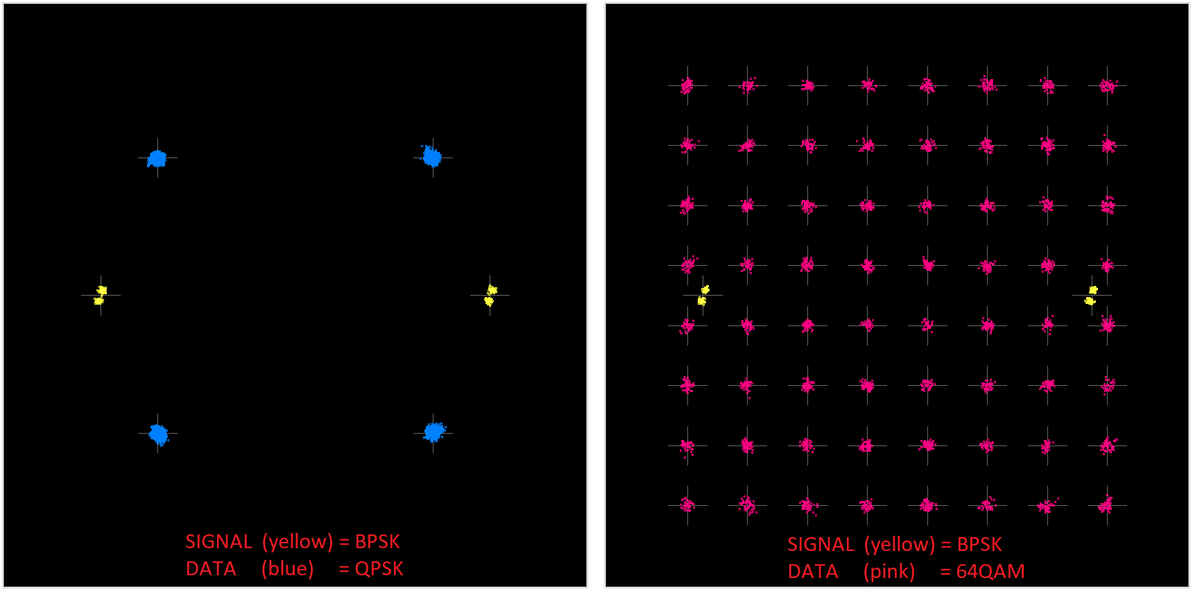
The wlan_modulator module begins the process of converting digital bits into IQ samples by a process called modulation. wlan_modulator turns coded bits from wlan_interleaver into constellation points based on the corresponding modulation scheme for the packet. The IEEE 802.11 specification requires several modulations for OFDM rates, including BPSK, QPSK, 16-QAM, and 64-QAM. The coded bits sent to wlan_modulator are used as indexes in the constellation map for each respective modulation.
The choice was made for IEEE 802.11 OFDM to have 48 data carrying subcarriers, and all subcarriers have the same modulation scheme. In the case of the 6Mbps rate, the subcarriers are BPSK modulated, meaning that each subcarrier only modulates 1 coded bit as BPSK. In this case wlan_modulator dequeues 1 bit per subcarrier, and uses that 1 coded bit as an index into the lookup table corresponding to the BPSK modulation, for example (-1 for 0-bit and +1 for 1-bit).
Similarly, as another example, the 54 Mbps rate uses 64-QAM as its modulation, meaning 6 coded bits are necessary per subcarrier to index the constellation mapping for 64-QAM. With 48 data subcarriers, wlan_modulator needs 6 coded bits for each of the 48 data subcarriers for a total of 288 coded bits per OFDM symbol.
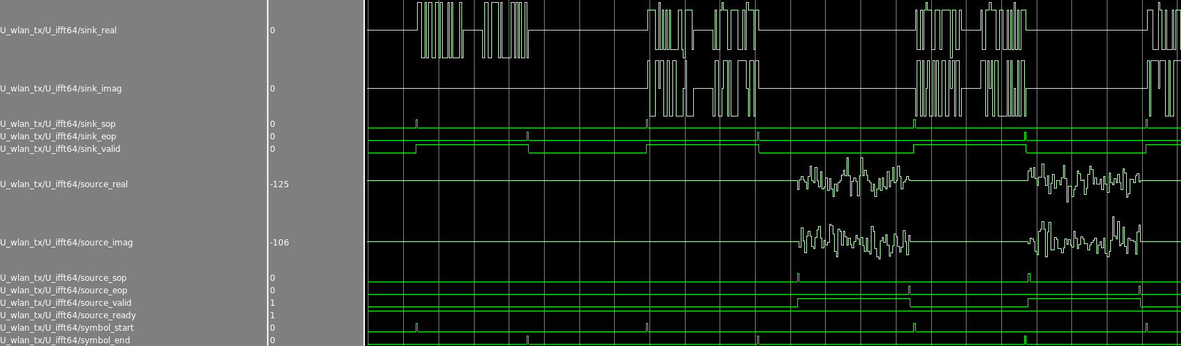
wlan_ifft64:
Once the wlan_modulator modulates coded bits into constellation points, the complex (having real and imaginary components) constellation points in IEEE 802.11 OFDM are turned into complex IQ samples by a simple inverse FFT. The inverse FFT is performed on the full 64 subcarriers (soon to be referred to as FFT bins), which includes 4 pilot tones, 48 data subcarriers, 1 DC bin, and 9 zero bins that help narrow IEEE 802.11 spectral side-lobes.
wlan_sample_buffer:
wlan_ifft64 generates the raw baseband IQ samples that get sent to an DAC for conversion to analog. IEEE 802.11 symbols are 4 microseconds long (assuming long guard intervals), but 64 IQ samples sampled out at 20MSPS is only 3.2 microseconds. The remaining 0.8 microseconds are used as a gap in between symbols to decrease Inter-Symbol Interference (ISI). The 0.8 microsecond gap which corresponds exactly to 16 IQ samples at 20MSPS is located at the beginning of each OFDM symbol period. The gap is however not left blank, instead the last 16 samples output by the inverse FFT are copied to the beginning of the OFDM symbol into the gap. The samples in the gap are called the Cyclic Prefix (CP). The phase is continuous between the end of the CP and the beginning of the 64 samples generated by the inverse FFT by virtue of the Fourier Transform being cyclic every 2*pi, in this case 2*pi is 64 samples.
The wlan_sample_buffer module is also used to create a 32 sample (1.6 microsecond long Cyclic Prefix) for 2 back-to-back Long Training Sequence repetitions.
wlan_tx_short:
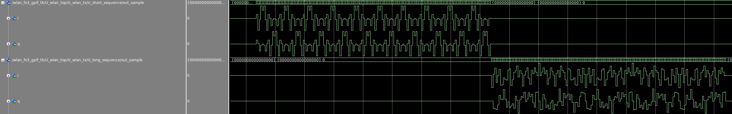
The wlan_tx_short module generates the 16 samples that defined the IEEE 802.11 Short Training Sequence. The STS phase is 8 microseconds long, and it is intended to help any receiver lock its automatic gain control (AGC), and gain a rough timing estimate of the packet; this topic is covered in the wlan_rx module.
wlan_tx_long:
The wlan_tx_long module generates the 64 samples defined as the IEEE 802.11 Long Training Sequence. The LTS phase is also 8 microseconds long. The sequence is intended for estimating center frequency offset, as well as reference for generating the initial equalizer parameters; this topic is covered in the wlan_rx module.
wlan_rx:
wlan_pll:
To ensure the modem can process RX samples as quickly as it receives them, part of the wlan_rx module runs at 4 times the clock rate of the sample rate (20 MSPS). Most of the OFDM receiver effectively runs in an 80MHz clock domain and requires its own PLL because of this.
wlan_agc:
This module informs the rest of the modem when it is detecting a burst; a sequence of high energy IQ samples is usually indicative of a digital packet. This module is written to allow the bladeRF-wiphy modem to either control manual gain control or to interpret the signals from an AGC. In the case of the bladeRF 2.0 micro xA9, the AD9361’s physical control GPIO pin ( adi_ctrl_out(0) ) can be used to inform the modem when the AD9631 has locked to a new gain setting. This external signal clues in the modem about when the IQ samples are likely to be stable. The module also informs the rest of the modem when it assumes nothing else is transmitting and the medium is clear. A decision it reaches by comparing the IIR filtered values of I^2 + Q^2 against an empirically determined value. Essentially, even when nothing is transmitting, a receiver listening to silence will not see 0 energy due to the thermal noise (basically the I and Q samples do not go to 0) so determining the magnitude of the IQ vector that reflects “radio silence” had to be empirically determined. For additional information about this topic and implementing an AGC, take a look at the GRCon-18 presentation about implementing an 802.11 compatible AGC on the original bladeRF https://www.youtube.com/watch?v=rwmfSVXo8K8 .
wlan_acquistion:
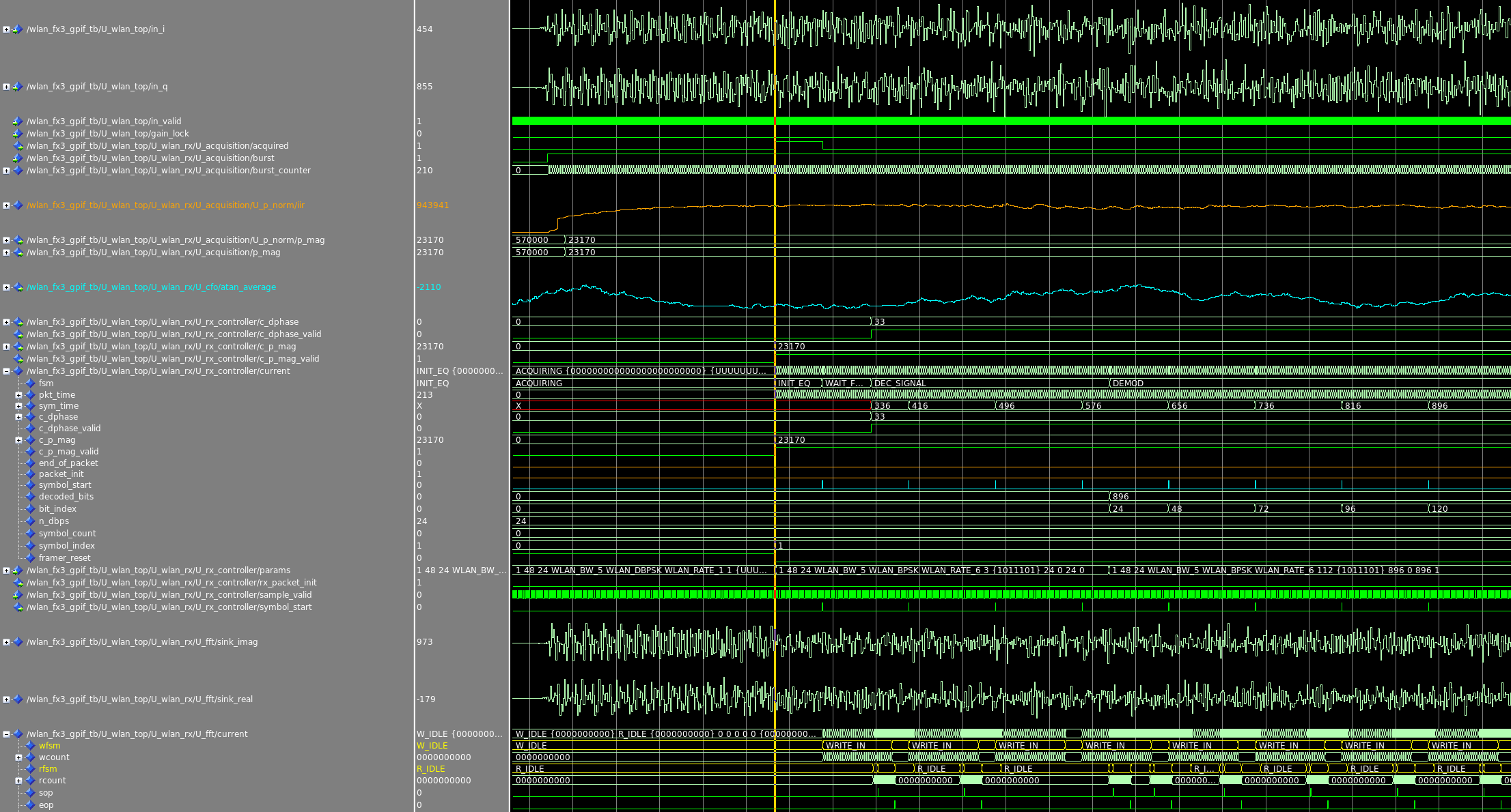
The acquisition module looks and tries to identify if the current burst is an 802.11 packet by analyzing patterns that are indicative of the presence of the 10 repetitions of the standard 802.11 short training sequence (STS), a BPSK modulated signal. The acquisition module also uses information passed to it from the AGC about the start of burst, and whether gain settings have changed. In case the AGC changes after the first several samples are received, the bladeRF-wiphy modem then ignores the few samples before the gains have locked — those samples are likely to be highly distorted by clipping and of little practical value except for starting the burst counter. The acquisition module is the first module to feature a burst counter, a counter that counts the number of samples since the beginning of the burst. Effectively the counter gives the modem a sense of how far along in a burst it is. Remember, the bladeRF-wiphy does not store any samples, it requires something similar to a clock (in this case the burst counter) to determine how to interpret IQ samples. The acquisition module asserts the acquired signal based on the Schmidl&Cox OFDM synchronization technique but only if the synchronization value peaks within a time-frame roughly around 12 microseconds into the burst. The synchronization value is based on the similarity of the previous 16 samples, against the average value of the preceding two 16 sample buckets. The value effectively starts to decrease after the 10th repetition of the short training sequence (STS) is compared against the 8th and the 9th repetitions. The accurate estimation of the end of the 10th repetition of the short training sequence (STS) is important because the modem uses it as a reference for the start time of each subsequent OFDM symbol, including the long training sequence (LTS) repetitions that follow the STS repetitions. In DSP terminology, the modem has now achieved symbol timing recovery.
To aid with fixed point arithmetic, the acquisition module calculates a value by which to scale the fixed point samples to ensure power normalization for the subsequent stages of the modem. If you are wondering why not just rely on the AGC, it is because the analog gain amplifiers controlled by the AGC can only do so much. It is up to the p_norm (power normalization) module to ensure the rest of the modem has power normalized samples.
wlan_cfo_estimate:
For example, when two separate physical 802.11 modems communicate, despite both of them intending to tune exactly to 2.412GHz, the two devices will likely tune to slightly different frequencies, likely on the order of a few hundreds or thousands of Hz. This is caused by impurities in quartz crystal oscillators used as references for Phase Locked Loops (PLL) and Local-Oscillators (LO). A quartz crystal oscillator’s error of a few parts per million at the typical frequency range of oscillators (10MHz to 40MHz) is propagated by the LO to the LO frequencies. As an example, a crystal’s tolerance (expressed in ppm) is propagated almost unaffected by the LO, meaning a 5ppm tolerance can be as much as 29kHz for an LO generating 5.8GHz. A DSP algorithm in the receiver has to then compensate for this. Fortunately, the CFO is easy to estimate by computing the phase difference between two subsequent identical OFDM symbols. The double repetition of the long training sequence found in the beginning of each 802.11 frame can be used to extract this CFO estimate.
The wlan_cfo_estimate module’s main output is a signal called cfo_atan_average. The cfo_atan_average signal is a set of 64 moving average windows of CFO estimates (output of the atan2() CORDIC). The first estimate corresponds to the phase difference between the 1st sample of the first LTS and the 1st sample of the second LTS, and so on and so forth until the 64th sample of the first and second LTSs. wlan_rx_controller snapshots this free running value at the correct moment, more on this later. The CFO estimate can then be used to undo the CFO; the actual CFO correction happens within the wlan_fft module, more on this later.
wlan_rx_controller:
The RX controller module contains a simple state machine that stalls the OFDM decoding pipeline until the SIGNAL symbol of an 802.11 packet has been successfully decoded. The SIGNAL comes right after the long training sequence, and it is always encoded at essentially the 6Mbps OFDM Modulation Coding Scheme (MCS) rate. The SIGNAL field however contains a 4-bit field that indicates the MCS of the remainder of the packet. The RX controller waits for the Viterbi decoder to finish decoding the SIGNAL symbol before sending OFDM symbols after the SIGNAL symbol further down the receiver pipeline. The Viterbi decoder takes a deterministic amount of time to complete, so the FIFO buffers can be sized accurately.
The RX controller maintains its own sample counter which it uses to calculate the appropriate time to snapshot and save cfo_atan_average, which is the CFO estimate provided by wlan_cfo_estimate. The optimal time to snapshot d_phase is when the moving average window in wlan_cfo_estimate is calculated based on samples at the tail end of the LTS. This effectively ensures the CFO is estimated on the LTS samples that are after the LTS’s Cyclic Prefix.
The power normalization value calculated by wlan_acquistion is also snapshotted and saved as correction_p_mag. The RX controller inverts the CFO estimate to create a signal (correction_dphase) that can be used to compensate for the CFO, more on this later in wlan_fft.
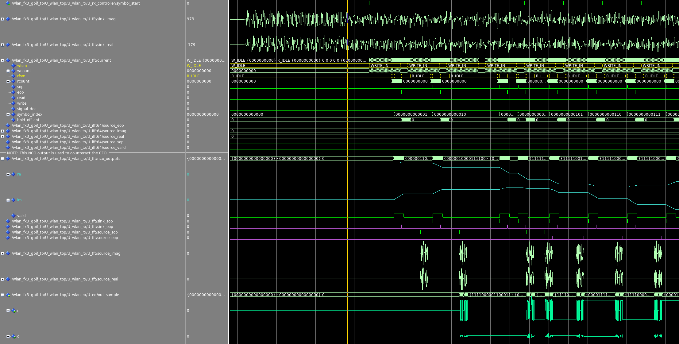
wlan_fft:
At the core of an OFDM demodulator is an FFT that takes time domain samples and converts them into frequency domain bins that correspond to OFDM subcarriers. The frequency domain subcarrier is essentially a simple phasor that is modulated using a standard IEEE 802.11 modulation such as: BPSK, QPSK, 16-QAM, 64-QAM, 256-QAM, etc.
To mitigate the effects of the center frequency offset (CFO), the receiver: estimates the CFO, inverts the CFO estimate to create a “correction phase”, and generates a complex tone based on the correction phase. Recall the wlan_rx_controller module computes and provides correction_dphase. The complex tone (e^{jwt}) is then multiplied in the time domain with the baseband IQ samples prior to being fed into the FFT. The complex tone is called complex because it only has one spectral element located at w in the frequency domain. Essentially, a time domain multiplication of the baseband IQ samples with the complex tone is a frequency domain convolution that “frequency shifts” the time domain samples to where they would approximately be if no CFO existed. The wlan_fft module uses the symbol_start signal from wlan_rx_controller to: #1) select which baseband IQ samples to correct then send to the FFT and #2) start the numerically controlled oscillator (NCO) that generates the complex tone used to correct samples in step #1.
For each OFDM symbol, which consists of 64 time domain IQ samples, the wlan_fft module outputs 64 “CFO corrected” frequency domain samples, each corresponding to a subcarrier.
wlan_cfo_correction:
Since the CFO correction is mostly handled by the wlan_fft module, this module performs the last correction step before equalization. The wlan_fft module scales samples using the power normalization value that was calculated by wlan_acquistion and snapshotted by wlan_rx_controller.
wlan_equalizer:
The wlan_equalizer module receives 64 power normalized “CFO corrected” frequency-domain samples per OFDM symbol. Before any demodulation can take place, one last reversible channel effect in particular has to be mitigated, and that is multipath. As an RF wave propagates, it reflects off walls, windows, surfaces, and essentially refracts around surfaces, culminating in multiple time-delayed copies of the original signal reaching a receiver. In effect, multipath is to wireless communication modems, as echoes or resonant rooms are to people speaking. In time-domain modulation techniques, methods like Least Squares (LS) equalization can be used to estimate a channel impulse response. This estimate is then used to create a filter that inverts (effectively, removes) the channel impulse response. With frequency domain techniques like OFDM, once received samples come out of the receiver’s FFT, there are no direct echoes to remove, instead multipath can be modeled as a per-subcarrier phase rotation and magnitude scaling. Put simply, multipath is modeled by a per-subcarrier phasor, or complex vector. The effects of multipath can then be modeled as a set of per-subcarrier complex vector multiplications.
S_{received} = C_{channel} * S_{transmitted}The effects of multipath are modeled and referred to as the channel impulse response (CIR). The CIR can be estimated by comparing each frequency-domain subcarrier bin (generated by FFT-ing received IQ samples) against the expected subcarrier’s value (defined by IEEE 802.11). The wlan_equalizer module takes a Zero Forcing approach by simply dividing the expected value by the frequency-domain bin computed from received IQ samples to produce an inverse channel impulse response.
Essentially, if S_{transmitted} is known (in 802.11 the constellation points of the LTS are defined), and S_{received} are the samples that come out of wlan_fft, the channel inverse estimate refered to as (C_{channel})^{-1} can be estimated simply by: dfrac{S_{transmitted}}{S_{received}}.
wlan_rx_controller ensures the first set of 64 subcarrier samples that the wlan_equalizer module receives belong to the second LTS symbol. In the INITIAL_ESTIMATE state, the wlan_equalizer module generates its initial equalizer parameters. These initial parameters, (C_{channel})^{-1}, are estimated by dividing the ideal samples (constant “T2”) by the baseband samples (signal “in_sample”) that were actually received. The per-subcarrier equalizer parameters are saved, and are recalled to correct every subsequent OFDM symbol’s subcarrier samples. Each subcarrier sample is corrected by multiplying it with its corresponding equalization parameter:
S_{equalizer} = S_{received} * (C_{channel})^{-1}
wlan_equalizer outputs one fewer OFDM symbol than it receives because the first symbol (the second LTS) it receives is used to calculate the initial equalizer parameters. Subsequent OFDM symbols are equalized then output by the wlan_equalizer module.
The wlan_equalizer module can also take a dfe_sample as an input parameter. This parameter is the constellation-clamped value it estimates it should have received. For example, if after equalization the resultant IQ sample is 0.9+j0.001, the binary soft decision module (wlan_bsd), will clamp it to +1 assuming a BPSK constellation. wlan_equalizer then calculates a new vector: {(C_{channel})^{-1}}_{next}= dfrac{hat{S}_{transmitted}}{S_{received}}= dfrac{constellation clamp (S_{received})}{S_{received}}.
To avoid rapid changes, the updated {(C_{channel})}^{-1} parameter can be weight-averaged with the previous value. This sort of equalization parameter updating, is known as Decision Feedback Equalization. It is useful for mitigating residual CFO, and for varying channel effects. The multipath induced channel impulse response estimate generally is not accurate for longer than the transmission time of its respective packet. However, fast moving objects (such as fan blades) can invalidate the initial equalizer parameter estimates before the packet is received. Those variations however, are much less pronounced between adjacent symbols, so the DFE equalizer can hopefully track the changing channel impulse response correctly.
As a side note, time-domain (single carrier) waveforms frequently use Least Squares (LS) equalization to approximate time-domain filter parameters to mitigate multipath. Those time-domain filter parameters effectively are time-domain conversions (FFT) of the inverse channel impulse response, which is generally thought of in frequency-domain terms. If those same LS time-domain filter parameters would be converted to the frequency-domain by an FFT, they would likely look similar to the frequency-domain derived equalizer parameters.
wlan_phase_correction:
In OFDM IEEE 802.11, 4 equally spaced out subcarriers are reserved as pilot tones. These pilot tones are time-varying but deterministic, and can be anticipated by the received. The pilot tones are used by wlan_phase_correction to estimate and mitigate any residual CFO.
When the wlan_phase_correction module receives an OFDM symbol, it extracts the pilot tones, and calculates a residual CFO estimate based on the difference in angle between the pilot tones’ expected and measured vectors. Ultimately, a single per-symbol phase correction vector is calculated and then applied to all subcarriers in the current OFDM symbol.
wlan_demodulator:
The wlan_demodulator module serves two purposes. Its primary task is to turn subcarrier baseband IQ samples into bits based on the modulation constellation point closest to the IQ sample. A lot of information can be lost if hard decisions are performed, as an example, with BPSK an IQ sample of 0.1+j0 would still be considered a +1, however it is a much weaker +1 than an IQ sample at 0.98+j0.03. To help the Viterbi decoder, wlan_demodulator produces a 3-bit certainty (or lack thereof) value for each bit it demodulates, this is called a Binary Soft Decision (BSD). The closer a demodulated BSD is to a decision boundary the less certain the decision is, and vice versa. It is important to keep in mind, constellation points are laid out in a way to minimize the Hamming distance between constellation points. For high order modulation schemes like 64-QAM, the 4 bits that comprise the constellation point are at different distances from decision boundaries, so each of the 4 binary soft decisions can have different certainty levels.
Secondly, the wlan_demodulator module provides the constellation point closest to the IQ sample back to wlan_equalizer so that wlan_equalizer can update its equalizer parameters as described in the wlan_equalizer section.
Ultimately, wlan_demodulator outputs the demodulated BSDs it calculates. The number of BSDs per symbol depends on the modulation scheme alone, a maximum number of 288 BSDs is output for MCSs using 64-QAM.
wlan_deinterleaver:
The demodulated BSDs are deinterleaved according to the IEEE 802.11 specification. IEEE 802.11 relies on interleaving to ensure that uncoded bits are not adjacent in frequency to avoid clusters of grouped bit errors. Viterbi decoder is generally not capable of handling adjacent groups of bit errors.
wlan_depuncturer:
The deinterleaved BSDs are rearranged to be passed to the Viterbi decoder. The wlan_depuncturer module reverses the puncturing that is done by the transmitter’s modulator. Puncturing is used in IEEE 802.11 to remove redundant bits at higher MCSs when a high SNR link decreases the need for error correction. More redundant bits (the ratio of coded to uncoded bits) decrease the rate “r” value of an MCS, which increases an MCS’s ability to correct errors.
wlan_viterbi_decoder:
The wlan_viterbi_decoder uses a Soft Viterbi Algorithm (SOVA) decoder. Due to common approachs such as traceback based Viterbi decoders, the decoded bits take a certain amount of clock cycles to be computed. The wlan_viterbi_decoder state machine flushes the Viterbi decoder when all relevant soft decisions have been provided, and waits for the decoded bits to become available. This lag is especially noticeable when decoding the SIGNAL symbol, or awaiting the final bytes of a PDU.
wlan_descrambler:
The wlan_descrambler module simply undoes the scrambling done by the transmitter’s scrambler. The SERVICE byte is always expected to be 0, so the descrambler finds a LFSR initializing value that meets the criteria. Each subsequent byte is descrambled with subsequent values of the LFSR.
Scrambling is useful for avoiding transmitting similar IQ samples sequentially because of repeated values (or low entropy data) in PDUs, such as: strings of zero bytes in typical TCP and UDP headers, or ASCII characters that essentially only encode about 6 bits of entropy per byte. Similar IQ samples repeated sequentially can temporarily distort the PAPR limits, and cause issues for the transmitter.
wlan_rx_framer:
The wlan_rx_framer module is the final state machine in the wlan_rx module. Initially the wlan_rx_framer decodes the SIGNAL symbol and verifies its integrity by checking the parity bit. The SIGNAL field’s MCS and length fields are decoded and asserted to the rest of the wlan_rx subsystem. Subsequently, the module assembles bytes coming from the descrambler into a PDU. These bytes are then saved into a temporary packet FIFO. Ultimately, wlan_rx_framer calculates a packet’s CRC and verifies whether it matches the frame check sequence (FCS) in the received packet. If the CRC matches the FCS, the packet is assumed to have been successfully decoded, and the packet is marked as valid in the temporary packet FIFO. wlan_rx_framer also determines whether a packet is addressed to the current modem, and whether the 802.11 frame type and subtype require an acknowledge frame (ACK) to be sent to the original transmitter. In case an ACK is required, wlan_rx_framer sets the ack_mac (the MAC address of the intended recipient of the ACK) and asserts ack_valid. The ack_mac and ack_valid are then written into a FIFO buffer the wlan_top module uses to generate an ACK packet directly in HDL on the FPGA. This step is necessary to meet strict acknowledge timing requirements in IEEE 802.11.
wlan_rx_packet_buffer:
The wlan_rx_packet_buffer is a double buffered FIFO that allows packets to be stored as they are being received. If a packet is successfully decoded, wlan_rx_packet_buffer asserts buf_params_valid as valid to inform the rest of the modem that a valid packet is present. In case it is determined that a packet is not valid, because the FCS check failed or because the packet’s energy was lost, wlan_rx_packet_buffer is instructed to clear the temporary buffer. wlan_rx_packet_buffer receives packets both from the DSSS and OFDM modules.
DSSS:
wlan_dsss_rx:
The IEEE 802.11 Direct-Sequence Spread Spectrum (DSSS) rates generally solely exist on IEEE channels 1 through 11, and are now referred to as legacy bitrates. However, despite the name, DSSS frames are still very popular even in 2020. The lowest DSSS bitrate is the 1Mbps rate. This rate occupies 22MHz of bandwidth, compared to the lowest OFDM rate, the 6Mbps rate, which occupies only 20MHz. This high level of redundancy makes DSSS frames inherently more resilient against bit and packet errors, of which there is a high potential in the 2.4GHz ISM band. The DSP algorithms for implementing DSSS rates are far simpler than those necessary for OFDM rates, however having one modem be able to decode both OFDM and DSSS rates requires some careful planning. The ideal lowest-common multiple for IEEE 802.11 DSSS rates sets the sample rate to either 11MSPS or 22MSPS. IEEE 802.11 OFDM rates however need a sample rate that is a multiple of 20MSPS. Due to the much higher resilient nature of DSSS rates, it then makes more sense to prioritize the performance of the OFDM rates, and use 20MSPS as the base sample rate for a combined IEEE 802.11 DSSS and OFDM modem.
wlan_dsss_despreader:
IEEE 802.11 DSSS packets consist of chips, which are spread-sprectrum modulated PDU bits. In DSSS, a single PDU bit is modulated then “spread out” into the many samples that define a chip. These chips have one particularly interesting property: a known chip sequence only has a high correlation value with its complex conjugate when the comparison window perfectly aligns the two chips. A slight time offset between a received DSSS chip and its known complex conjugate is enough for the correlation value to be very low. The correlation value is also very low when the complex conjugate of the known DSSS chip is correlated with noise and non-DSSS samples. The process of comparing correlation values between received IQ samples and complex conjugates of DSSS chips to find a chip is known as despreading. An IEEE 802.11 DSSS modem uses the preamble, called the Start of Frame Delimited (SFD), which consists of 144 alternating -1 and +1 chips to recover symbol timing.
IEEE 802.11 DSSS uses a positive correlation to denote a ‘1’ bit, and uses a negative correlation to denote a ‘0’ bit. The bits are then concatenated, turned into bytes, and stored into a FIFO to recreate the PDU.
If the system were sampling at 22MSPS, despreading the DSSS chips would be a simple mix of addition and subtraction of historical values dictated by the DSSS chip pattern. However, because the decision was made to sample at 20MSPS, the 22MSPS DSSS chip pattern has to be resampled to 20MSPS. This resampled chip is defined by the constant called “preamble” in wlan_dsss_despreader.
wlan_dsss_despreader performs a full DSSS chip correlation on each incoming sample and the previous 19 samples.
wlan_dsss_peak_finder:
The wlan_dsss_peak_finder module is responsible for estimating symbol timing by finding which of the 20 possible time offsets (or bins) corresponds to the highest correlation magnitude. The bin index that is the mode (output signal “out_mode_bin”) is assumed to be the correct timing. It is then selected as the bin whose correlation output is used to reconstruct the PDU, bit by bit.
wlan_dsss_demodulator:
The IEEE 802.11 CCK rates use Differential Binary Phase Shift Key (DBPSK) to encode PDU bits. For N number of PDU bits, N+1 DBPSK chips are necessary. A PDU bit “0” is demodulated if the current chip is the same value as the previous chip, for example a -1 chip followed by a -1 chip. Conversely a PDU bit “1” is demodulated if the current chip is different (Differential) from the previous chip, for example a -1 chip is followed by a +1 chip.
As these bits are received, the wlan_dsss_demodulator module descrambles the bits before outputting out_bits and out_valid.
wlan_dsss_rx_framer:
The wlan_dsss_rx_framer module initially waits for the appropriate moment to snapshot the bin index that is the mode. Once snapshotted it is provided as an estimate to the rest of the DSSS RX chain. Ultimately wlan_dsss_demodulator is responsible for concatenating descrambled bits from wlan_dsss_demodulator into PDU bytes, and ensuring the CRC in the packet header and the FCS in the packet match. PDU bytes are sent to a temporary buffer in wlan_rx_packet_buffer, until the packet’s FCS can be validated.
Current status

The HDL bladeRF-wiphy modem is a IEEE 802.11 compatible implementation. bladeRF-wiphy can currently only synthesize for the bladeRF 2.0 micro xA9. The bladeRF 2.0 micro xA4’s FPGA is too small to fit all parts of the DSSS RX, and OFDM RX and TX modems. The modem can be fully simulated in Modelsim.
Features
- IEEE 802.11 compatible FPGA based PHY receiver and transmitter
- Compatible with bladeRF 2.0 micro xA9 (and bladeRF 2.0 micro xA9 THERMAL)
- Linux mac80211 MAC integration
- RX and TX monitor mode support
- Hardware Distributed Coordination Function (DCF) allows quick turn-around time ACKs
- High-performance equalizer – implements Zero Forcing (ZF) and optionally Decision Feedback Equalizer (DFE)
Modulation schemes:
DSSS – CCK
OFDM – 20MHz (6Mbps, 9Mbps, 12Mbps, 18Mbps, 24Mbps, 36Mbps, 48Mbps, 54Mbps)
Bandwidths:
5MHz (useful for 802.11p)
10MHz
20MHz
Modulation constellations:
DSSS-CCK DBPSK
OFDM-BPSK
OFDM-QPSK
OFDM-16-QAM
OFDM-64-QAM
Convolution encoder rates:
r=1/2
r=2/3
r=3/4
Mission
The development goal of this project is to fill the gap of a single open-source modem project that can leverage Linux’s open-source mac80211.
Hopefully the release of this open-source modem will provide developers and researchers with a single project solution to learn about OFDM, DSSS, 802.11, MACs.
In the grand scheme of things, it is important that the open-source community has the tools necessary to transparently interact with technologies that are the basis of our modern communication methods.
Future
Currently many of the wireless protocols we use and depend on in our daily lives are opaque pieces of technology. Researchers and developers are unable to conduct experiments and critical research.
While the modem currently works on the bladeRF, it is hoped that the bladeRF-wiphy project will be the beginning of a revolution in open-source communication and the basis of open-source chips. For a thriving community focusing on open-source chip development please take a look at the Google affiliated Skywater-PDK project.
Advanced features and inquiries
For inquiries regarding high performance demodulation, Crest Factor reduction, Digital Predistortion (DPD), Decision Feedback Equalization, re-modulation techniques, support and licensing, please contact [email protected] .
Please contact [email protected] for details regarding an intensive 2 day training course on the full IEEE 802.11 stack covering everything between Schrodingers equations and HTTP, including: applied DSP and statistics, DSSS, OFDM, PHYs, MACs, Linux, mac80211.
Notes
The source code is released under the GPLv2 license on Github at https://github.com/Nuand/bladeRF-wiphy/ . To report bugs, feedback, and features requests please join the bladeRF Slack ( channel #bladeRF ).
To contact us, support this effort, or contribute, please contact [email protected] or consider joining the #bladeRF channel in bladeRF Slack.